
Product / Manufacture
The manufacturing plan stays attached to the design.
A CAM job is created from the active part in the Manufacture workspace. Stock, work coordinate system, tools, operations, simulation, and post output live beside the model they came from instead of in a separate file that drifts.
Manufacture workspace
Stock, tools, operations, and simulation in one place.
Open the Manufacture workspace, create a job from the active part, and select the machine or post target. Define stock and set a work coordinate system the operator can actually reproduce at the machine.
Name setups and operations for the manufacturing intent — the face, the pocket, the bolt-circle drilling — rather than generic sequence numbers. The names are what a second person reads when the job comes back six months later.
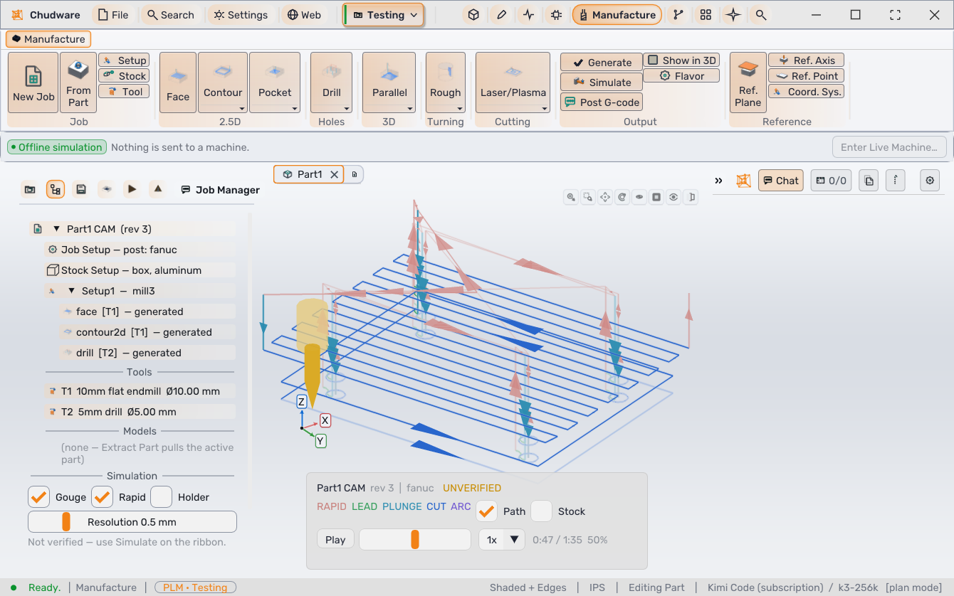
Stock removal
Review what the job leaves behind before posting code.
Simulation sweeps every cutting move through a stock model, draws the programmed path, and lets you scrub back and forth before you post.
Stock removal · illustration
Job setup
Everything the toolpath depends on is explicit.
Stock defines what exists before the first cut. The work coordinate system defines where the machine thinks the part is. Both are declared, not inferred.
- FacingEstablish a reference face on raw stock.
- PocketingClear enclosed material to depth.
- ContouringFinish profiles and outside walls.
- DrillingHole patterns from the model's own features.
Tools come from the project library, and 3D operations are available where a surfaced form needs them. Operations are added in process order, which is the order the machine will run them.
The hand-off
From part to posted code.
Create the job
Open the Manufacture workspace, create a job from the active part, and select the machine or post target you intend to use.
Declare stock and WCS
Define the stock the operator will actually load and a work coordinate system they can reproduce on the machine.
Build operations in process order
Select tools from the project library and add facing, pocketing, contouring, drilling, or 3D operations, named for the manufacturing intent.
Simulate before posting
Generate the toolpath and simulate with tool, holder, stock, and rapid moves visible. Investigate collisions, unexpected remaining stock, gouges, and rapids through fixtures. A generated path is not automatically a safe path.
Post for one machine
Post G-code only for the machine and controller profile you are running. Compare units, work offsets, tool numbers, spindle limits, and the first moves before the file leaves your desk.
Where the line is
Chudware prepares and inspects the work.
Simulation, collision inspection, and remaining-stock review exist so problems appear before a spindle turns. They are preparation tools. They do not certify a program.
Dry-run and single-block procedures at the machine still apply, according to your shop's safety process.
Operator responsibility
The operator remains responsible for machine setup and execution. Inspect stock, tool, setup, simulation, and posted code before anything runs.
This also applies to work the AI copilot prepares: it may build CAM operations and output, but actions affecting a physical machine require explicit operator review and control.
Next
Keep the program, the part, and the decision trail together.
Posted G-code is one more artifact a project revision carries.